

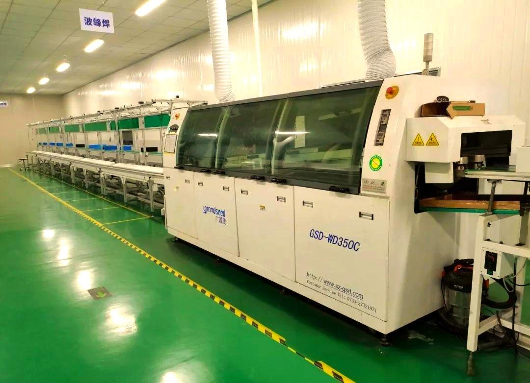
Almost no modern board is purely SMT or purely through-hole. Most are mixed, and the mix is a design decision made long before assembly. But the choice is still worth understanding precisely, because it determines your placement cost, your test strategy, your rework options and — in high-vibration or high-thermal-stress products — your field failure rate.
This guide compares the two processes on the variables a buyer and a design engineer actually weigh, and explains when mixed technology is the correct answer rather than a compromise.
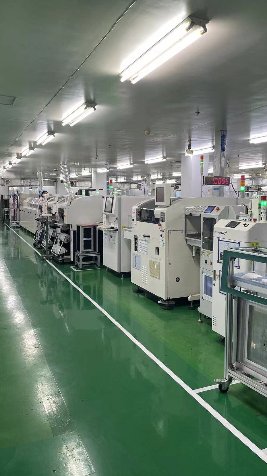
The Two Processes
SMT (surface mount technology) places components directly onto pads on the board surface, then reflows solder paste in an oven. Components are small, leadless or short-leaded (resistors, capacitors, QFN, BGA, SOIC).
Through-hole technology (THT) inserts components with leads through drilled holes, then solders them — by wave, selective or hand soldering. Components are larger and mechanically anchored (connectors, transformers, electrolytic capacitors, power devices, switches).
| SMT | Through-hole | |
|---|---|---|
| Mounting | Component sits on the pad | Leads pass through the board |
| Soldering | Reflow (paste) | Wave, selective or hand |
| Component size | Small to very small | Larger |
| Board area used | Low — components sit flat | Higher — holes and lead spacing |
| Mechanical strength | Joint strength only | Mechanical anchoring through the board |
| Rework | Hot air, hot plate, difficult on BGA | Desoldering, generally easier |
| Inspection | AOI, X-Ray for hidden joints | Visual, plus X-Ray for barrels |
| Typical cost per joint | Lower at volume | Higher; more manual steps |
| Density | High | Low |
What Is the Difference Between SMD and Through-Hole Components?
An SMD (surface mount device) is a component designed to be soldered onto a pad: no leads that pass through the board. Examples: 0402 resistors, QFN microcontrollers, BGA packages, tantalum capacitors.
A through-hole component has leads designed to pass through holes in the board: DIP ICs, radial electrolytic capacitors, pin headers, terminal blocks, transformers.
The component dictates the process. You cannot wave-solder a BGA, and you cannot reflow a transformer with 2 mm leads without a custom fixture.
What Does SMT Assembly Mean?
SMT assembly is the process of building a board using surface mount components:
- Solder paste is printed through a stencil onto the pads
- SPI (solder paste inspection) checks volume, height and alignment
- A pick-and-place machine places components from reels or trays
- The board passes through a reflow oven, where the paste melts and forms joints
- AOI inspects the result; X-Ray checks hidden joints on BGA and QFN
The process is highly automated, which is why it scales: the same line builds ten boards or ten thousand with the same setup, and the per-unit cost falls with volume.
What Is the Difference Between SMT and THT?
SMT is the mounting and soldering technology for surface mount components. THT (through-hole technology) is the equivalent for leaded components. They are parallel processes, not versions of each other.
One clarification worth making because it causes confusion in quotations: SMT and SMD are not the same thing. SMT is the technology; SMD is the device family. A quote for "SMT assembly" means the process, and it may or may not include through-hole content.
When Is Through-Hole Still the Right Choice?
Five situations where a solder joint is not enough
Five situations where through-hole wins:
- Mechanical load. Connectors that take insertion force, terminal blocks that take screw torque, and anything that will be pulled or pushed should be through-hole. A surface-mount connector on a board that gets cables yanked out is a warranty claim.
- Vibration and shock. Through-hole leads anchor mechanically; SMT joints rely on solder alone. Automotive, industrial and appliance boards often specify through-hole for this reason.
- Thermal cycling. Large components with CTE mismatch benefit from compliant leads that flex rather than transferring stress to the joint.
- Power dissipation. Power devices can use the board and a heatsink through a lead frame, and the thermal path through a through-hole is often better than a surface pad.
- Availability and cost. Some parts are simply not available in SMD — high-voltage capacitors, some relays, transformers.
When Is SMT the Right Choice?
Five reasons density wins
- Density — you need more components in less area
- Small packages — QFN, BGA, 01005 are SMT only
- Automation — SMT scales with volume and needs less labour
- Weight and height — flat components allow thinner products
- Cost at volume — per-joint cost is lower once the line is set up
Component-to-Process Selection Table
Most design reviews do not need a philosophy of SMT versus through-hole. They need a per-component decision. Use this as the starting classification, then override it where the mechanical or thermal argument is stronger.
| Component type | Default process | Why | Exception worth knowing |
|---|---|---|---|
| Chip resistors and capacitors (0402–1206) | SMT | Cost per joint, density, no mechanical load | Large electrolytics are the exception, not the rule |
| QFN, DFN, BGA, LGA | SMT only | No leads to insert; thermal pad needs reflow | BGA needs X-Ray, and often via-in-pad |
| SOIC, QFP, SOT, MSOP | SMT | Fine pitch, high pin count | Rare in through-hole equivalents |
| Pin headers and board-to-board connectors | Through-hole | Takes insertion and extraction force repeatedly | SMT versions exist for low-force, low-cycle use |
| Terminal blocks and screw terminals | Through-hole | Screw torque and wire pull load the joint | SMT terminal blocks need a mechanical anchor |
| Board-edge connectors (card edge, USB) | Either | Depends on retention design | USB-C receptacles are often SMT with through-hole anchors |
| Radial and axial electrolytics | Through-hole | Mass and lead anchoring; also thermal | SMD aluminium electrolytics are fine at low mass |
| Transformers, inductors (wound) | Through-hole | Weight, lead anchoring, isolation distance | SMD power inductors are SMT |
| Relays and switches | Through-hole | Mechanical actuation load | SMD relays exist but are limited in rating |
| Power devices with heatsink tab | Either | Depends on thermal path and package | TO-220/TO-247 are through-hole or screw-mounted |
| Fuses and fuse holders | Through-hole | Replacement force, safety | SMD fuses for board-level protection |
| Crystals and oscillators | SMT | Small, no load | Watch out for thermal profile sensitivity |
| Shielding cans and frames | SMT or clip | Low load, but needs a ground connection | Clip-style frames often need through-hole tabs |
Three practical rules fall out of the table:
- Mechanical load decides through-hole. If a part will be pulled, pushed, torqued or inserted repeatedly, a solder joint alone is the wrong anchor.
- Pin count and pitch decide SMT. Above roughly a few dozen pins at fine pitch, through-hole stops being manufacturable at reasonable cost.
- Everything else is cost and availability. Once the first two rules are applied, choose what is cheaper and in stock.
Mixed Technology: The Normal Case
Most real boards use both. The design decision is which components go where, and the assembly decision is the sequence.
The usual sequence for a mixed board:
- SMT side first (paste, place, reflow) — often the denser side
- Through-hole insertion
- Wave, selective or hand soldering for the through-hole parts
- Cleaning, inspection, test
Two consequences buyers should know:
- Through-hole on a mixed board is usually hand or selective soldered, which is a labour step with its own cost and quality variability.
- The second side of a double-sided SMT board requires a second pass — either reflow with components glued, or a reflow that does not disturb the first side. This roughly doubles process time.
Where the Decision Goes Wrong
Choosing SMT for a connector that takes mechanical load. It passes functional test and fails in the field when the cable is pulled.
Choosing through-hole for density reasons. It consumes board area and adds drilling cost that was not in the original estimate.
Forgetting that mixed assembly needs two processes. A quote that assumes full SMT pricing for a board with 40 through-hole parts will be revised.
Ignoring thermal mass. A board with large through-hole components and a thick copper layer needs a different reflow and wave profile. This is discovered at first article if nobody planned for it.
Underestimating hand-soldering variability. Hand-soldered joints vary more than machine joints. If the product is safety-critical, specify selective soldering or a soldering standard.
Assuming rework is equal. Reworking a BGA needs hot air or IR and a reballing capability; reworking a through-hole part needs a desoldering tool. Both affect the rework policy.
Decision Checklist
- Classify every component: mechanical load, thermal load, density, availability.
- Specify through-hole for anything that takes insertion, torque or pull force.
- Specify SMT for density and fine-pitch packages.
- For mixed boards, confirm the assembly sequence and which side goes first.
- Ask whether through-hole content is hand, wave or selective soldered — and the quality control for that step.
- Confirm the reflow and wave profiles account for board thermal mass.
- Agree the inspection plan: AOI, X-Ray, visual, and who performs the through-hole inspection.
- Agree the rework policy, including who is qualified to rework which package type.
FAQ
Can a board be entirely SMT?
Yes, and many consumer boards are. The limit is not the process but the components: if the design needs a terminal block, a wound transformer or a part that takes repeated insertion force, something has to be through-hole or mechanically anchored. Connector retention is the usual reason a "pure SMT" board ends up mixed.
Why is through-hole still used at all?
Because a lead passing through a hole anchors the part mechanically, not just electrically. That matters for insertion force, screw torque, vibration, drop and thermal cycling. No solder joint alone replicates it, which is why connectors and power parts stay through-hole across industries.
Is SMT cheaper than through-hole?
At volume, per joint, usually yes — placement is automated and the line scales. But the comparison is per programme, not per joint: a board with few components may cost more in stencil and programming than it saves in labour. Ask for both scopes priced on your actual BOM.
Can through-hole parts be reflowed instead of wave soldered?
Sometimes — the technique is pin-in-paste, where paste is printed into the hole and the part is placed and reflowed with the SMT side. It works for small through-hole content and limited pin counts, and it removes a process step. It is not a general substitute for wave or selective soldering on connectors with large thermal mass.
Why YC PCB
- 20+ years of PCB and PCBA manufacturing, exporting to 20+ countries
- Both SMT and THT/DIP in-house, including mixed-technology assembly
- BGA, QFN and Micro-BGA support with X-Ray inspection for hidden joints
- AOI, electrical test, ICT and FCT scoped per project
- BOM management and component sourcing, with alternates confirmed before build
- DFM/DFA review before production, including assembly sequence for mixed boards
- ISO 9001 and UL certification; NDA available for customer IP
Get a Quote — Send your Gerber, BOM, CPL and assembly drawing, and tell us which components are through-hole. Our engineers reply with the assembly plan, DFM notes and pricing within one working day.


 English
 Japanese
 French
 German
 Spanish
 Italian
 Portuguese
 Russian
 Dutch
 Turkish
