

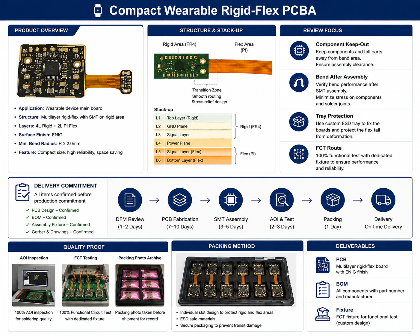
Rigid-flex boards are expensive to prototype and expensive to re-spin. The reason is structural: a rigid-flex is not a rigid board with a flexible tail glued on. It is one continuous stack-up in which some layers are present everywhere and others stop at a boundary — and every decision about where they stop has mechanical and electrical consequences.
This guide covers the design decisions that determine whether a rigid-flex can be built as drawn: which layers run continuous, how to design the transition zone, and what mechanical data the fabricator needs before quoting. YC PCB produces rigid-flex assemblies where components and vias sit in rigid sections and interconnects flex between them.
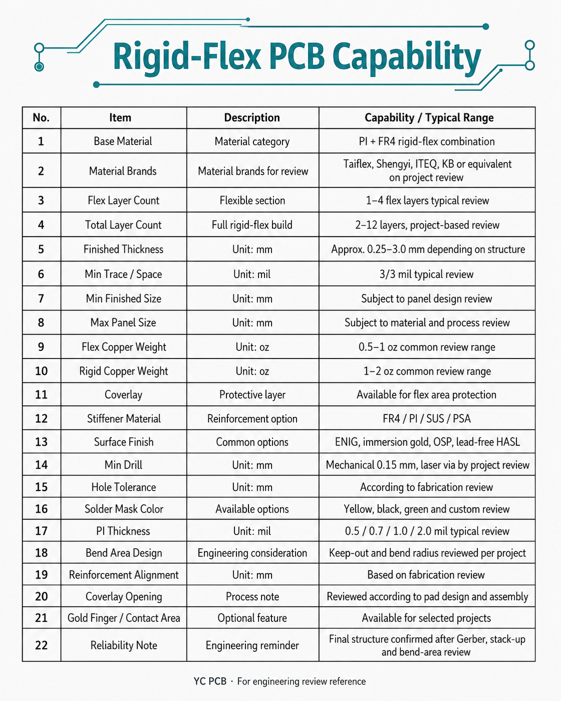
What Makes a Rigid-Flex Different
| Aspect | cURL Too many subrequests by single Worker invocation. To configure this limit, refer to https://developers.cloudflare.com/workers/wrangler/configuration/#limits | Flex PCB | Rigid-Flex |
|---|---|---|---|
| cURL Too many subrequests by single Worker invocation. To configure this limit, refer to https://developers.cloudflare.com/workers/wrangler/configuration/#limits | Uniform rigid laminate | Uniform flexible laminate | Rigid sections + flexible sections, bonded |
| Vias | Anywhere | Avoided in bend areas | Confined to rigid sections |
| Componenten | Anywhere | Avoided in bend areas | Confined to rigid sections |
| Cost driver | Area, layers, finish | Area, layer count, coverlay | Number of rigid sections, lamination cycles, transition complexity |
| Assembly | cURL Too many subrequests by single Worker invocation. To configure this limit, refer to https://developers.cloudflare.com/workers/wrangler/configuration/#limits | Needs carrier or support | Standard SMT on rigid sections |
| Typical use | Most electronics | Tight spaces, one-time folds | Compact modules, camera assemblies, medical and aerospace |
The value of rigid-flex is integration: it replaces a flex cable plus two connectors plus two rigid boards with one part. The cost of that integration is a more complex stack-up and less tolerance for design errors.
Which Layers Run Continuous?
Three layer classes, one spine
A rigid-flex stack-up has three layer classes:
- Continuous layers — run through both rigid and flexible regions. Usually the flex core (polyimide with copper on both sides).
- Rigid-only layers — added in the rigid sections only, to reach the required rigid thickness and layer count.
- Bonding layers — no-flow or low-flow prepreg and adhesive that joins the rigid sections to the flex core, and must not flow into the bend area.
The most common stack-up error is treating the rigid sections as independent boards joined by a flex tail. In a proper rigid-flex, the flex core is the mechanical spine, and the rigid sections are built onto it.
Confirm on the drawing:
- Which layer numbers exist in the flexible region (usually fewer)
- Where each rigid-only layer starts and stops
- The bond ply type and its flow characteristics
- The final thickness in rigid and flexible regions — they are different numbers
Transition Zones: Where Rigid-Flex Actually Fails
Why the boundary, not the bend, is the failure site
cURL Too many subrequests by single Worker invocation. To configure this limit, refer to https://developers.cloudflare.com/workers/wrangler/configuration/#limits.
cURL Too many subrequests by single Worker invocation. To configure this limit, refer to https://developers.cloudflare.com/workers/wrangler/configuration/#limits
- cURL Too many subrequests by single Worker invocation. To configure this limit, refer to https://developers.cloudflare.com/workers/wrangler/configuration/#limits. cURL Too many subrequests by single Worker invocation. To configure this limit, refer to https://developers.cloudflare.com/workers/wrangler/configuration/#limits.
- cURL Too many subrequests by single Worker invocation. To configure this limit, refer to https://developers.cloudflare.com/workers/wrangler/configuration/#limits. cURL Too many subrequests by single Worker invocation. To configure this limit, refer to https://developers.cloudflare.com/workers/wrangler/configuration/#limits.
- cURL Too many subrequests by single Worker invocation. To configure this limit, refer to https://developers.cloudflare.com/workers/wrangler/configuration/#limits. cURL Too many subrequests by single Worker invocation. To configure this limit, refer to https://developers.cloudflare.com/workers/wrangler/configuration/#limits.
- cURL Too many subrequests by single Worker invocation. To configure this limit, refer to https://developers.cloudflare.com/workers/wrangler/configuration/#limits. Adhesive flow at the boundary creates a stiff fillet. Its size affects where bending actually starts.
- Leave a keep-out in the coverlay and stiffener. The transition needs a defined flexible window, not an incidental one.
- Round the rigid-section corners that face the bend. A square corner is a crack initiation point.
The transition zone check sheet
Use this when you review the design before release. Every row is a drawing check, not a manufacturing check — which means every row is cheap to fix at this stage and expensive to fix after tooling.
| Check item | What a good design shows | What goes wrong when missed |
|---|---|---|
| Via clearance from transition | No via closer than one bend radius into the rigid section | Barrel cracks at the boundary, opens after thermal cycling |
| Component clearance | Keep-out covering the transition plus one bend radius | Solder joint fatigue on the nearest part |
| Layer termination stagger | Rigid-only layers ending on two or three different lines | Abrupt stiffness change, peeling at the bond line |
| Bond ply flow allowance | Flexible window sized larger than the finished opening | Window narrows after lamination, bend radius effectively shrinks |
| Coverlay and stiffener keep-out | Explicit keep-out region, dimensioned on the drawing | Stiffener edge lands in the bend, local strain spike |
| Rigid corner radius | Radius on every corner facing the flexible region | Crack initiation at the corner, often after assembly |
| Copper balance across the boundary | Continuous copper or symmetric distribution at the transition | Warp and delamination at the interface |
| Test pad placement | All test pads inside rigid sections | Probe damage to the flex region during test |
The 3D data the fabricator actually needs
A 2D drawing cannot describe a rigid-flex. The part exists in three dimensions, and three questions can only be answered from a model:
- Where is the part constrained? Screw bosses, connector seats and enclosure walls determine where the part must stay flat. A bend that a 2D drawing permits may be impossible once the enclosure is considered.
- What is the installed bend radius? The radius in service is set by the mechanical assembly, not by the drawing. Without the installed position, the fabricator cannot tell you whether the design is inside the flex guidance.
- Where does the assembly fixture grip? cURL Too many subrequests by single Worker invocation. To configure this limit, refer to https://developers.cloudflare.com/workers/wrangler/configuration/#limits.
cURL Too many subrequests by single Worker invocation. To configure this limit, refer to https://developers.cloudflare.com/workers/wrangler/configuration/#limits.
cURL Too many subrequests by single Worker invocation. To configure this limit, refer to https://developers.cloudflare.com/workers/wrangler/configuration/#limits
cURL Too many subrequests by single Worker invocation. To configure this limit, refer to https://developers.cloudflare.com/workers/wrangler/configuration/#limits.
| Input | cURL Too many subrequests by single Worker invocation. To configure this limit, refer to https://developers.cloudflare.com/workers/wrangler/configuration/#limits |
|---|---|
| cURL Too many subrequests by single Worker invocation. To configure this limit, refer to https://developers.cloudflare.com/workers/wrangler/configuration/#limits | cURL Too many subrequests by single Worker invocation. To configure this limit, refer to https://developers.cloudflare.com/workers/wrangler/configuration/#limits |
| cURL Too many subrequests by single Worker invocation. To configure this limit, refer to https://developers.cloudflare.com/workers/wrangler/configuration/#limits | cURL Too many subrequests by single Worker invocation. To configure this limit, refer to https://developers.cloudflare.com/workers/wrangler/configuration/#limits |
| Static or dynamic bend, with cycle count if dynamic | Drives copper type and bend radius limits |
| 3D model or mechanical drawing | Shows how the part sits in the enclosure and where it is constrained |
| Assembly boundary — where the part is gripped | Prevents designing flexibility where the fixture clamps |
| Connector positions and mating direction | Affects stiffener and reinforcement requirements |
| Rigid section thickness | Determines layer build in those sections |
| Surface finish per region | ENIG and hard gold are often used in different areas |
| Any requirement for shielding or EMI layers | Changes the stack-up and the layer count |
| Panelisation and carrier design | Thin flex regions need carrier support through assembly |
Where Rigid-Flex Designs Break Down
Stack-up drawn as if all layers run everywhere. The quote comes back for a thicker, more expensive board, or the build fails at the transition.
Bend radius set by the enclosure, not by the stack-up. A rigid-flex with a thick rigid section can only bend so far. If the enclosure demands a tighter radius, the design needs a longer flexible region, not a thinner one.
Vias placed by rule, not by region. DRC does not know where the bend is. The transition keep-out has to be a design rule, or it will be violated.
Adhesive flow unaccounted for. Bond ply flows during lamination. If the flexible window is sized exactly to the drawing, the flow may narrow it.
Assembly treated as if the part were rigid. Rigid-flex parts need carriers or fixtures. If the assembly process grips the flexible region, the part is damaged before it ships.
Test access forgotten. Rigid sections are where test pads belong. If the design does not reserve them, test coverage drops.
Design-to-Order Checklist
- Define rigid and flexible regions on the stack-up drawing, layer by layer.
- Identify which layers are continuous and where rigid-only layers terminate.
- Place all vias and components inside rigid sections, at least a bend radius from the transition.
- Stagger layer terminations at the transition to avoid an abrupt stiffness change.
- Define the flexible window with keep-outs in coverlay and stiffener.
- State bend type, radius, direction and cycle count.
- Provide a 3D model or mechanical drawing showing the installed position.
- State the assembly boundary and the fixture concept.
- Confirm the bond ply type and its flow behaviour with the fabricator.
- Agree panelisation and carrier design before tooling.
Where Most Rigid-Flex Guides Stop
They explain the concept and the layer structure, and stop before the handoff. The three points that decide whether the project goes smoothly:
cURL Too many subrequests by single Worker invocation. To configure this limit, refer to https://developers.cloudflare.com/workers/wrangler/configuration/#limits. cURL Too many subrequests by single Worker invocation. To configure this limit, refer to https://developers.cloudflare.com/workers/wrangler/configuration/#limits.
cURL Too many subrequests by single Worker invocation. To configure this limit, refer to https://developers.cloudflare.com/workers/wrangler/configuration/#limits. cURL Too many subrequests by single Worker invocation. To configure this limit, refer to https://developers.cloudflare.com/workers/wrangler/configuration/#limits.
cURL Too many subrequests by single Worker invocation. To configure this limit, refer to https://developers.cloudflare.com/workers/wrangler/configuration/#limits. cURL Too many subrequests by single Worker invocation. To configure this limit, refer to https://developers.cloudflare.com/workers/wrangler/configuration/#limits.
Veelgestelde vragen
cURL Too many subrequests by single Worker invocation. To configure this limit, refer to https://developers.cloudflare.com/workers/wrangler/configuration/#limits
cURL Too many subrequests by single Worker invocation. To configure this limit, refer to https://developers.cloudflare.com/workers/wrangler/configuration/#limits.
cURL Too many subrequests by single Worker invocation. To configure this limit, refer to https://developers.cloudflare.com/workers/wrangler/configuration/#limits
Not through-holes. A plated hole is a rigid inclusion and will crack where the part bends or where strain concentrates at the transition. Vias belong in rigid sections, or in a stiffened area of the flex that never bends. If a design absolutely needs an interconnect in a flexing area, that is a signal that the part should be split differently.
What file format should I send with a rigid-flex RFQ?
Gerber and drill for the electrical layers, a stack-up drawing that defines rigid and flexible regions layer by layer, and a STEP model of the part in its installed position. Add the bend line locations, radii and direction. Without the 3D data, the fabricator can quote the build but cannot confirm that the bend is achievable in the enclosure.
Why is a rigid-flex re-spin so expensive?
Because the cost sits in tooling, lamination cycles and qualification, not in material. A stack-up change usually means new bond ply, new press parameters and a new first-article approval. That is why the transition zone and the layer termination lines deserve a review before release rather than after the first build.
Why YC PCB
- 20+ years of PCB manufacturing, including rigid-flex builds with components and vias in rigid sections
- FPC and rigid-flex reviewed at DFM stage: transition zones, bend windows, stiffener and coverlay confirmed before tooling
- Multilayer rigid sections up to the high layer counts used in compact modules
- ENIG and hard gold finishes for contacts and mixed-surface requirements
- Impedance control available on both rigid and flex sections with a dedicated stack-up
- AOI and electrical test on bare boards; X-Ray, ICT and FCT for assembly projects
- ISO 9001 and UL certification; NDA available for customer IP
Get a Quote — Send your Gerber, layer stack-up with rigid and flex regions, bend requirements and 3D or mechanical drawing. Our engineers reply with a feasibility review, DFM notes and pricing within one working day.


 Dutch
 English
 Japanese
 French
 German
 Spanish
 Italian
 Portuguese
 Russian
 Turkish
