
Copper Substrate PCB for High-Power LED Thermal-Electrical Separation Copper PCB.
Copper substrate PCB for high-power LED applications that need stronger heat spreading, controlled insulation structure, and stable small-batch to production delivery.
PCB manufacturing experience
On-time delivery, 10027 orders
Compliance documentation
Complaint rate from audit records

Can We Build It? Can We Deliver It?



Choose Your Copper Base PCB Procurement Mode
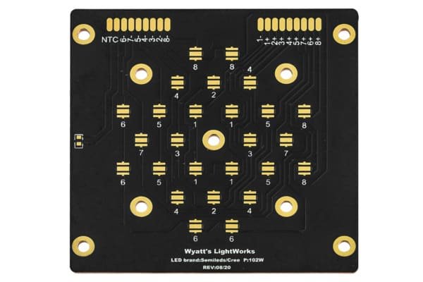
Flashlight LED Module

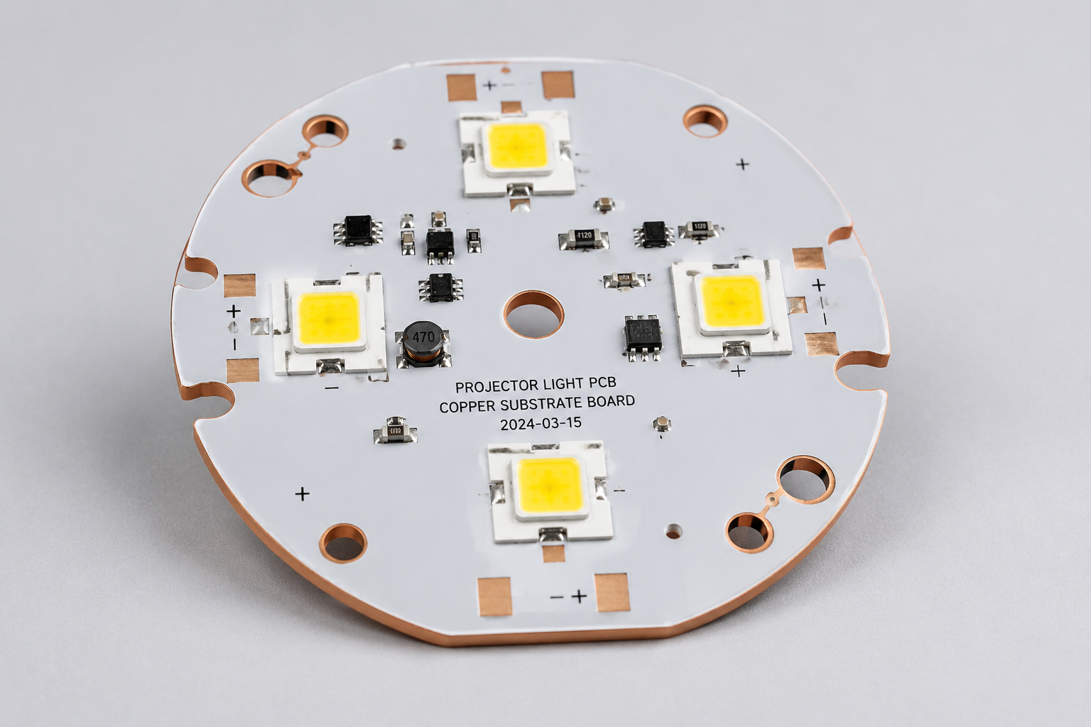
Projector Light PCB
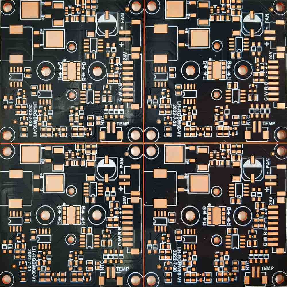
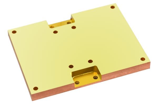
Thermoelectric Separation Board
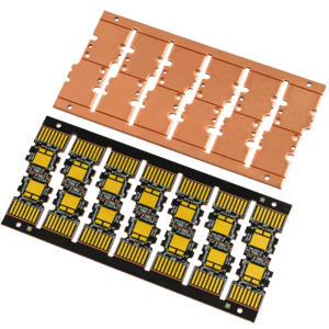
Copper Base LED PCBA
Copper Base PCB Product Table
| Image | Product | Product Type | Structure | Surface Finish | Key Check | Lead Time | Quote |
|---|---|---|---|---|---|---|---|
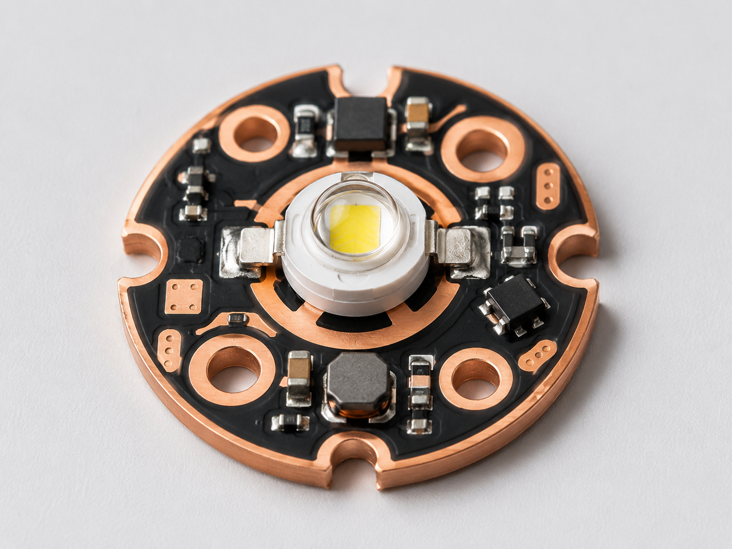 |
Copper Substrate Board for Flashlight YC-CU-FL |
Flashlight LED module | 1-3mm copper base | OSP / ENIG / silver plating | Thermal pad + polarity | 1-3 days after approval | |
|
Copper Substrate Board for Projector YC-CU-PRO |
Projector LED board | Custom copper stack-up | ENIG / silver plating by review | Heat source + isolation | 1-3 days after approval | |
|
Thermoelectric Separation Copper Substrate Board YC-CU-TS |
Separated thermal / electrical path | Isolation structure | ENIG / silver by review | Clearance + withstand | 1-3 days after approval | |
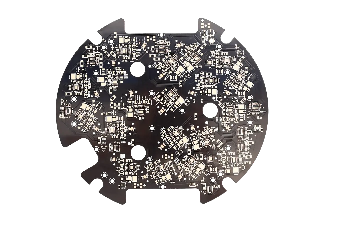 |
Copper Substrate Board for Stage Lights YC-CU-STAGE |
Stage light module | 1-3mm copper base | OSP / ENIG / silver plating | Heat spread + finish | 1-3 days after approval | |
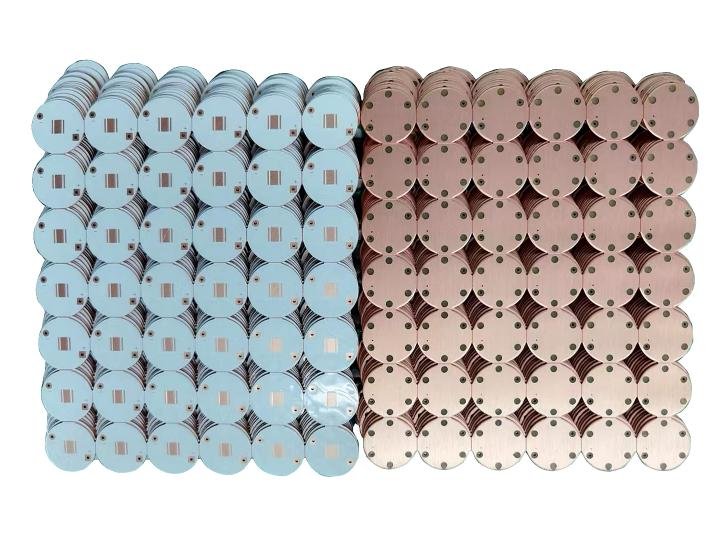 |
Copper Substrate Board for Mobile Lighting YC-CU-MOB |
Mobile light LED board | 1-3mm copper base | OSP / ENIG / silver plating | Outline + connector | 1-3 days after approval |
Final manufacturability depends on copper thickness, dielectric structure, heat load, LED pad design, routing tolerance, and assembly scope.

Copper Material & CNC Machining

PCB Exposure Process

QC Inspect
When Copper Base PCB Makes Sense
vs. Standard FR4 PCB
Copper Base PCB
vs. Aluminum PCB
Copper Base PCB Application Gallery
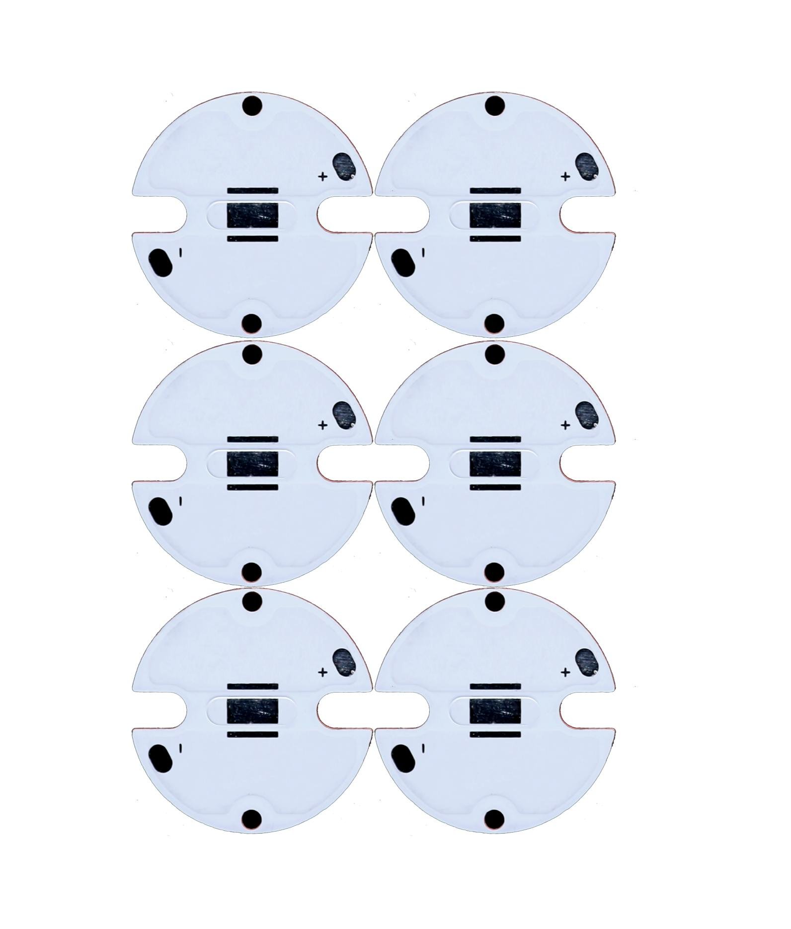
Flashlight Copper PCB
Projector Copper Substrate
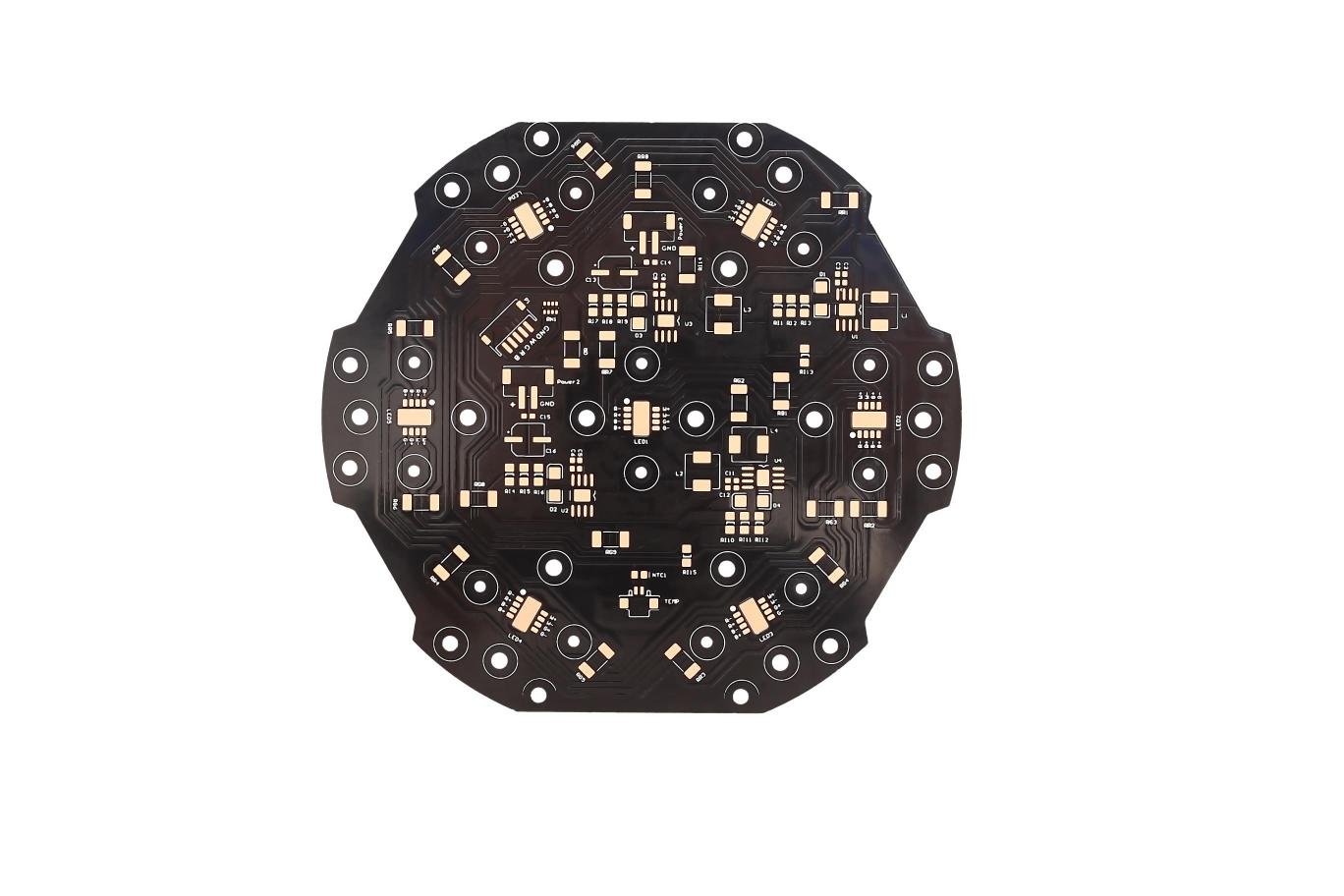
Stage Light Copper PCB
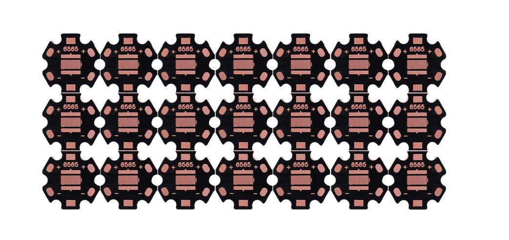
Mobile Lighting PCB
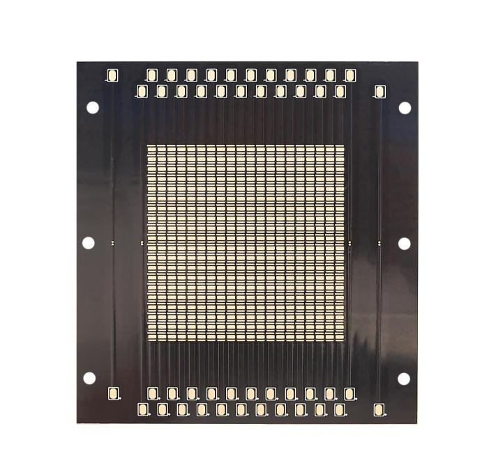
Thermoelectric Separation Board
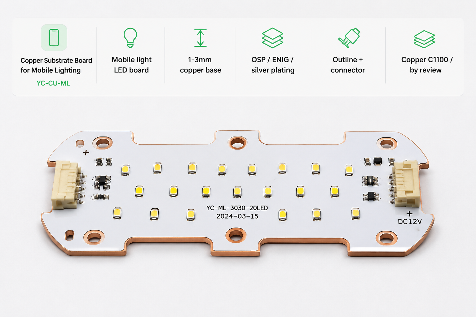
Copper Base PCBA
Copper Base PCB Design Review Before Production
Copper base PCB requires a reviewable decision trail. We confirm manufacturability, risk points, and lead time before production release instead of giving an unsupported delivery promise.
| Product Type | Copper Thickness | Thermal Conductivity | Fastest Lead Time |
|---|---|---|---|
| Standard Copper Base PCB | 1–4 oz | 1.0–3.0 W/m·K | 1-3 days after approval |
| High Thermal Conductivity PCB | 1–6 oz | 3.0–8.0 W/m·K | 3-5 days after approval |
| Copper Base LED PCBA | Custom | Custom | 5-10 days by BOM |
Copper Base PCB RFQ Requirements
Confirm the basic manufacturing range before quotation: copper substrate, stack-up, thermoelectric separation, surface finish, outline forming, and assembly requirement.
Copper PCB RFQ First. Engineering Review Next.
Send the core information first. Stack-up, thermal route, isolation, and assembly details can be confirmed after file review.
12-Month Copper PCB Delivery Performance
| Project Type | 12-Month On-time Rate | Sample Order Count | Main Bottleneck | Risk Control |
|---|---|---|---|---|
| Standard Copper Base PCB | 97.3% | 7270 sample / small-batch orders | Copper stock + CNC forming | Material confirmation before order release |
| Thermoelectric Separation PCB | 95.8% | 428 engineering orders | Stack-up review + isolation requirement | DFM and sample approval recommended |
| Copper Base LED PCBA | 96.5% | 580 PCBA orders | BOM sourcing + aging test schedule | Component confirmation before SMT |
Copper Base PCB Stack-up, Thermal, and Isolation Data
| Copper PCB Route | Base Thickness | Dielectric / Isolation Layer | Circuit Copper | Surface Finish | Thermal Conductivity | Best Fit |
|---|---|---|---|---|---|---|
| Standard Copper Base PCB | 1-3mm typical | FR4 / thermal dielectric | 1-3oz by review | OSP / ENIG / silver plating | 5.0 W/mK reference by stack-up | Flashlight, mobile lighting, LED modules |
| Thermoelectric Separation PCB | 1.5-2mm typical | Ceramic / insulation layer | By current and layout | ENIG / silver plating by review | 2.5-6.0 W/mK by isolation layer | Projector, stage light, high power LED |
| Copper Base LED PCBA | Custom | Custom by LED power and insulation | By electrical load | Per assembly process | Custom; confirm by Gerber + BOM | Finished LED modules |

Workshop / Copper Processing

Cross-section / Stack-up

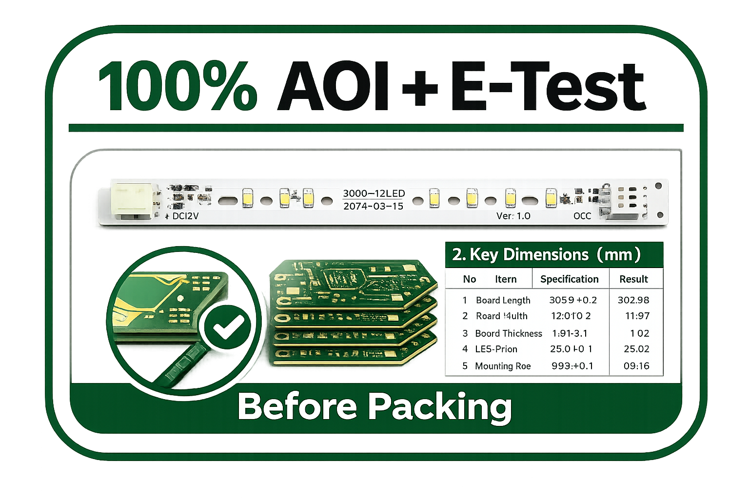
AOI / Electrical Test

LED Assembly / Aging
Review Before Copper Substrate PCB Production
Heat Path
Review copper base, thermal pad, heat source, and contact surface.
Electrical Isolation
Check thermoelectric separation, creepage, clearance, and withstand needs.
CNC / Mould Forming
Check outline, slots, mounting holes, V-Cut, burr risk, and panel handling.
Engineering Feedback
Typical feedback after complete Gerber, heat source notes, and assembly requirements are received.
Fabrication, LED Mounting, and Testing
PCB Fabrication
Copper base, dielectric, circuit layer, solder mask, finish, routing, and test.
LED / Component Sourcing
LED, resistor, connector, driver IC, and standard components by BOM.
Assembly & Test
SMT, DIP, LED mounting, polarity check, functional test, and aging test.
Traceable Delivery
Packing photos, inspection records, shipping documents, and after-sales review.
LED Sourcing, SMT Assembly, and Aging Test Scope
Copper base LED PCBA cost depends on both PCB stack-up and BOM strategy. Confirm component sourcing mode before formal quotation.
Component Supply Mode
Customer-supplied, YC-sourced, or mixed sourcing are supported after BOM review.
Standard SMT Range
Standard assembly route supports 0.4mm pitch and above. Finer pitch requires review.
Rework / Defect Target
Target rework rate ≤ 0.5% after stable pilot run and approved process window.
Long-Term Component Supply
Approved suppliers, qualified alternative components, and rolling forecasts help minimize the risk of supply disruptions.
Copper PCB Project References
Flashlight Module Case
Eastern Europe lighting customer. Copper substrate board used for high-lumen flashlight modules.
Projector / Stage Light Case
High-power stage light project using thermoelectric separation copper substrate route.
Quality Contact
Add a real quality or engineering contact for serious B2B buyers.
Request a Copper Base PCB Quote
Send product type, quantity, delivery target, copper substrate requirement, thermal route, contact information, and Gerber files. Engineering requirements can be confirmed after file review.
Email: sales@ycelectronic.com | Website: ycpcbs.com
Short RFQ Form
Request Copper Base PCB Quote
Fill the core fields first. Attach Gerber, drill, BOM, heat source map, LED layout, and drawings after the email window opens.
 English
  Japanese
  French
  German
  Spanish
  Italian
  Portuguese
  Russian
  Dutch
Dutch  Turkish